
FILTER SYSTEMS
The facts
regarding biological filter systems are:
The best systems are self cleaning drum filter systems. They are expensive. If you are not wealthy, forget them. Bead/sand filter systems are also
expensive. Get one if you want and can
afford it. The cheapest actually
effective systems are the submerged bio-media systems. I have built and designed many of them, some
for my own ponds (currently I have 6 in operation) and others for other ponders
(the largest filter system I have designed was for a 52,000 gallon pool
system). After over 30 years experience
with watergardening, I have designed and built a gravity fed submerged media
biofilter that incorporates the best of my own and other’s ideas that I have
distilled over the years. This filter
works. I have proved that. It is also cheap as compared to commercial
systems of comparable capacity. In
addition, it as low maintenance as any submerged media biofilter I have
seen. I present it to you as a
realistic permanent low maintenance system for your watergarden. The plan:
A submerged media
biofilter system incorporating a gravity feed side drain and skimmer with
low/easy maintenance mechanical filtering, high efficiency degassing trickle
filter and water polishing basket. Also including a provision for UV algae
control. All vessels except the trickle filter stage incorporate cone bottom,
which facilitate easy cleaning. See conepage.html
. The filter is fed
by two 3” pvc lines, one from a side drain and one from a skimmer. It is
designed to provide adequate filtering for a heavily stocked 2,700 gallon water
garden. It could be fed by a bottom drain but in my opinion bottom drains are
best used for dumping to waste rather than feeding into biofilters since the
amount of organic materials coming through bottom drains will overload most
submerged biofilters. I am fortunate in
the case of this particular pond in that the lot slopes away from the pond so
that even with the biofilter being buried at ground level, enabling gravity
feed to the filter system, the biofilter chambers can be drained to a lower
part of the yard ( I would point out here that I have five other water gardens
populated with koi that have submerged pumps and above ground biofilters). Gravity fed
biofilters have as an added attribute, the ability to locate the pump at the
end of the filter, thus reducing pump maintenance, since the pump is working in
already filtered water. Of course the filter design given here can be used in
an above ground operation, simply by locating the main pump in a skimmer or
flooded suction sump or even submerged in the pool. I have included herein a
design for an above ground 4 vessel filter system. Theory of
operation: Conventional
wisdom assigns the responsibility of conversion of ammonia (which is the result
of fish biology) to harmless nitrates to two types of bacteria, Nitrosomonas
and Nitrobacters. Notwithstanding more recent research that disputes the actual
identity of the bacteria responsible for the conversion, it is accepted that
bacteria of some sort does in fact convert the ammonia to harmless
nitrates. At any rate, the bacteria need
a place to grow and interact with the pool water in order to accomplish this task.
In fact, all surfaces submerged in a water garden, even the inside of pipes and
pool surfaces provide a place for such bacteria to grow. A biofilter generally
provides oodles of surface area for the bacteria to flourish. This area is
provided by the “media” in the biofilter. Commercial biofilter media is
expensive, far more expensive, in my opinion, than it should be. The media
chosen must allow free flow of water and not become easily clogged, be easy to
clean when necessary, and be CHEAP. In this filter design I have used 200 psi ¾
inch pvc pipe, cut into 1 inch pieces. While cutting a 10 foot piece of PVC
pipe into 120 pieces can produce a few blisters, it is a relatively cheap way
to make bio media. I accomplish this task using a miter saw. Cost is about $15.00 a cubic foot, as it
takes eleven 10 foot pieces of 200 psi 3/4 pvc to make a cubic foot of media.
Per my calculations, one cubic foot of such pvc pieces provides 56 square feet
of bio film area. This comes to 3.73
square feet of surface area per dollar.
For comparison with commercial bio media, Bio-Barrels are available that
provide from 26 ft2 to 64 ft2 per ft3 at a
cost range of from $31 to $55 (average about 1 square foot per dollar).
Commercially available Bio Balls provide from 98 ft2 to 160 f2
per ft3 for a cost range from $26 to $39 (averaging about 4 square
feet of surface per dollar). The
commercial bio Balls provide about the same surface area per dollar than the
pvc in a smaller package, but they are harder to clean than the pvc. Operation of the
filter: The filter system
is constructed of four 55 gallon and one 30 gallon plastic drums. Water enters
the first filter stage (called a vortex filter) via two 3” pvc pipes, fed by
gravity from the pool. Elbows in the vessel direct the water flow to move
around the vessel in a circle, or vortex. This action results in much of the
suspended solids falling out of suspension into the cone bottom of the
container where they can be easily drained away on a regular basis. Next, the
water enters the mechanical filter funnel where additional solids are filtered
out before entering the first biofilter media vessel in an upflow filtering
action. The water then passes to a third vessel wherein it passes through a
downflow biofilter media. Both media vessels
contain upwards of two cubic feet of bio media, providing 224 square feet of
biofilm surface area. The next stage is
a collection chamber, which includes no filter media, but does allow monitoring
of the water level flowing throughout the system. The main pump then moves the
water to the top of the degassing trickle filter/water polishing vessel. This
is a 30 gallon plastic drum that includes a cubic foot of pvc media that while
remaining wet, is also bathed in oxygen, which provides not only a boosted
biofilter action but also a means for nitrates to leave the pool environment.
Air induction is guaranteed via the operation of a fan that constantly feeds
air into the media. Degassing is accomplished via splashing as the entering
water falls into the polishing basket contained inside the drum, and also as
the water passes through the media. As the water
enters the trickle filter container, it is “polished”. This is accomplished
through a small waste basket lined with cotton batting, which removes very
small particles, leaving the pool with a “polished” quality. The design allows
for the “polisher” to simply overflow into the trickle filter media when
clogged, thereby causing no interruption of the pool bio filtration. The water then passes through the aerated
trickle filter media before finally exiting to the pond via a waterfall. Main pump protection is provided by a mercury
float switch located in the collection chamber or pump reservoir that will shut
off power to the main pump any time water level in the pump reservoir drops to
a predetermined level.
Because this is a
gravity fed filter system, special consideration is needed to provide for
clogging of the mechanical filter. If the mechanical
filter in the vortex vessel should become clogged, a mechanical filter bypass
pump is actuated by a liquid level switches in the second vessel. A red warning
lamp is also turned on by these switches to give notice that the mechanical
filter element needs cleaning. The
float level switches are wired so that when the water level in the second filter
vessel drops below a predetermined level, the bypass pump is turned on, along
with the signal light. If the flow is
increased enough for the water level in the same vessel rises back to normal,
another float switch turns off the bypass pump.
This operation will cycle on and off until the mechanical filter is
removed and cleaned. Since the power to
this circuitry is controlled by the main pump protection float switch as well,
should the water level in the main pump collection chamber drop to it’s predetermined
level, all pumps will be off until the water level rises back to normal. MODIFICATIONS: You can build
this system with modifications and still have a “state of the art” submerged
media biofilter system. The following
changes are possible: 1.
Eliminate
the mechanical filter bypass pump and the circuitry necessary to operate it,
but keep the mechanical filter. This
modification will save some money, first on materials and second on operation,
since there would be no bypass pump using electricity. The disadvantage would be that you would have
to more closely monitor the mechanical filter, since if it becomes clogged, the
water in the pump resevoir will drop and the main pump will shut off, reducing
or stopping flow through the biofilter.
This would not be good for the bacteria in the media. 2.
Eliminate
both the bypass pump AND the mechanical filter.
Because the media is of the free flow type you would rarely have much in
the way of reduced flow through the system. Disadvantage: more gunk will make it into the biomedia,
requiring more often cleaning. 3.
Add more
biofilter vessels. Adding more vessels
will increase the biological filtering capacity of the system, something that
you might need if you way overstock with fish.
Disadvantage: cost of the additional drum and uniseals and pvc pipe, and
the need to acquire more bio media.
Also, you would need more room to accommodate more barrels. My drums
cost me $24 each (used, but steam cleaned). 4.
Eliminate
1 biofilter vessel and operate with just one.
Obviously this would cost less to build and require less room. Disadvantage: Submerged biological media must
be cleaned periodically. When cleaned,
it may take several weeks for the media to effectively convert ammonia to
nitrates. If you only have one vessel,
your fish may be adversely affected after you have cleaned the filter
media. The reason I have two media
vessels is so that I can rotate cleaning of media by several weeks so that the
system continues ammonia conversion. If you already have a submersible pump you can
place it in the pump reservoir, instead of acquiring a new pump. You could
eliminate the forced air fan from the trickle filter, but the filters
efficiency will suffer. Such fans only
cost around $12 and are very cheap to run.
PICTURES AND DETAILS:
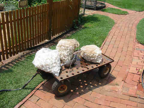
Here are three
bags of the filter medial made up of 1" pieces of 3/4 inch 200 psi pvc
pipe. Be sure to rinse the media before installing.
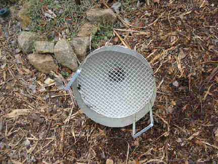
This is a picture
of the mechanical filter funnel showing the grid that supports the mechanical
filter element. The grid is made from
ceiling panels that are made for be fluorescent lights. They are available at Home Depot, etc. The
mechanical filter element is made from the blue furnace filter material sold at
many hardware suppliers such as Home Depot. This is NOT a fiberglass product,
which should be avoided.
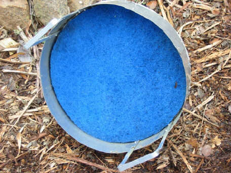
Here is the funnel with the mechanical filter element
installed.
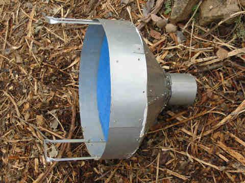
This is a side
view of the funnel. The "neck" of the funnel is sized to easily fit
inside a pvc coupling for 4" pvc pipe.
The cone of the funnel is made using the cone designer elsewhere in this
website.
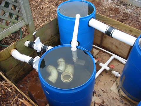
This is the
vortex vessel where the mechanical filter funnel will be installed. Note the
mechanical filter bypass pump (Pondmaster 1800) and the 2" pvc pipe that
will carry water to the second vessel whenever the mechanical filter becomes
clogged. Also note the pvc elbows that direct the incoming water to move in a
circular direction around the vortex vessel. One of the 3” incoming lines
originates from a side drain in the pool and the other from a skimmer.
This picture shows the mechanical filter installed in
the vortex vessel.
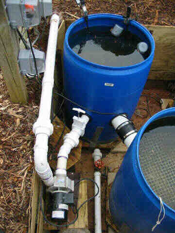
This
picture illustrates the position of the sequence main pump and the plumbing that
enables its removal for cleaning.
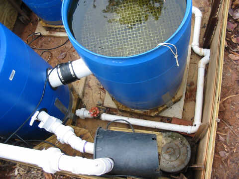
This
is how the sequence pump motor is protected with a cut-out plastic pot. Also illustrated is the drain plumbing from
the pump reservoir container.
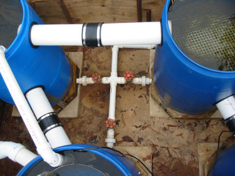
Here
is a picture of the drain system plumbing for vessels 1 through 3. One can also see the 4 inch pvc connection
between vessels 2 and 3.
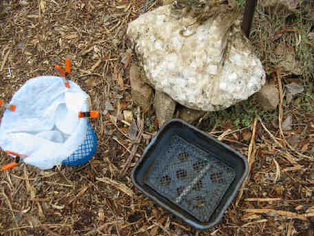
On
the left is the small mesh wastebasket lined with cotton/poly batting that is
the “water polishing” filter. On the
right is a plastic dishpan with a mesh bottom in which the wastebasket sits
inside the trickle filter container. On the top is a bag of 1” pieces of 200psi
pvc pipe that will be the trickle filter media.
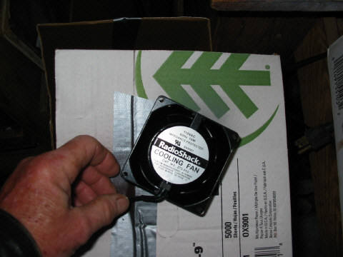
This
is an example of a computer type cooling fan used to pump air into the trickle filter.
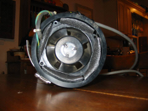
This
is a similar fan inserted into a rubber pipe connector with pieces of pipe
insulation foam inserted as air seals.
The
rubber pipe connector installed on the trickle filter container with the fan
inside.
This
is the trickle filter container showing the plumbing for the UV filter
installation in summer. Flow through the
UV is adjusted via the gate valve on the left.
In the picture above the UV has been replaced by a section of pvc pipe. I always remove my UVs in the winter and
store them. The UV that fits in where
the pvc pipe section is in the photo is a Pondmaster 20 watt unit. Water is kept flowing through the UV plumbing
via the pvc pipe section in order to prevent freezing. The large gate valve is for total flow
adjustment.
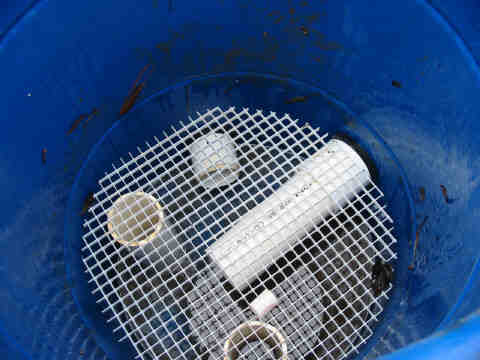
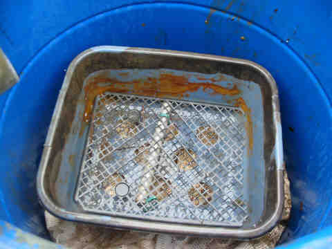
This
is a shot into the bottom of the trickle filter. At the top is the 3” pvc drain pipe that
exits to the waterfall. The long 3” pvc
pipe entering from the upper right is the air induction pipe from the fan. The other pvc pipes shown are only for
support of the grid.
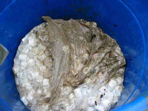
This
is the same shot as above except that the 1 cubic foot of pvc media has been
placed on the grid.
This is the support for the polishing filter.
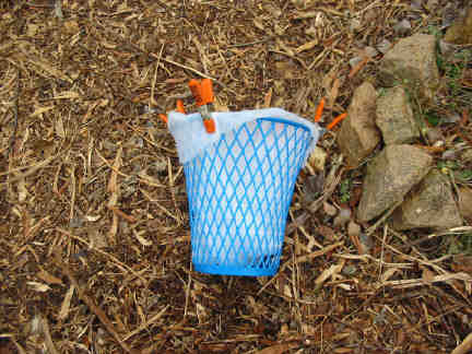
The polishing filter, with batting installed.
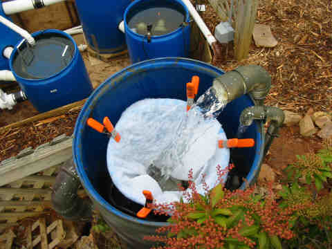
The
degassing/water polishing/trickle filter in operation. Note the camouflage paint treatment of the
pvc pipes.
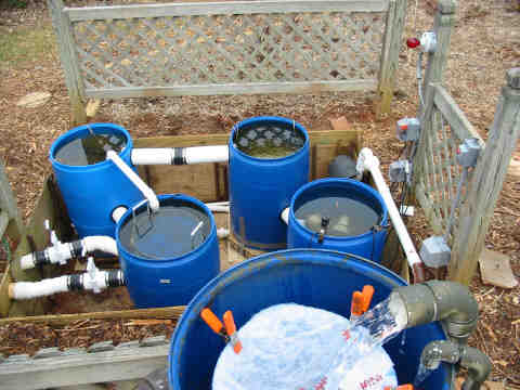
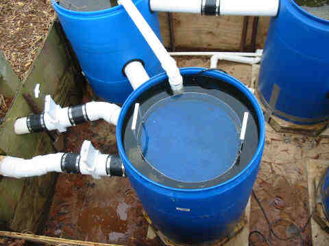
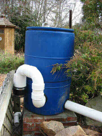
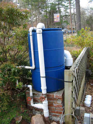
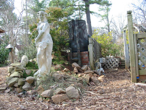
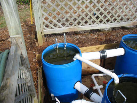
Another
view, showing the proximity of the gravity fed filter system vessels.
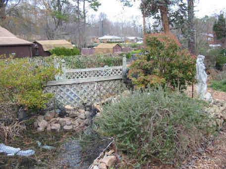
Looking
towards the waterfall and trickle filter hidden behind the shrubbery.
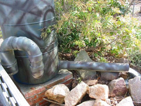
The
camo painted trickle filter discharge before addition of rocks.
Another
view of the camouflaged trickle filter.
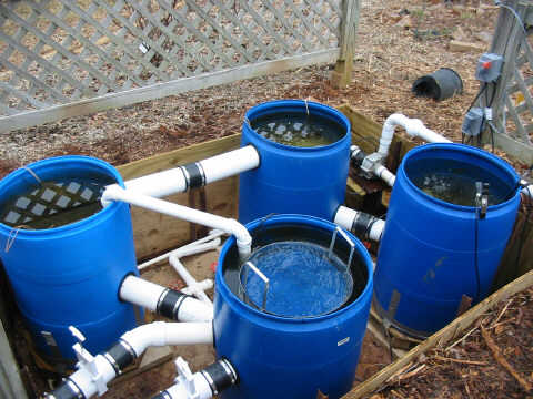
Overall
view of the gravity fed submerged media filter system.
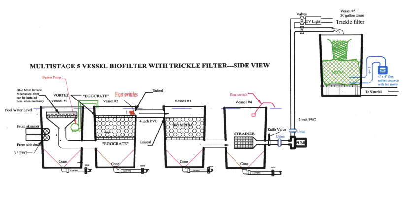
Schematic
of the gravity fed submerged media biological filter system. To be gravity fed, the tops of the drums
should be about 1 inch above the pond water level.
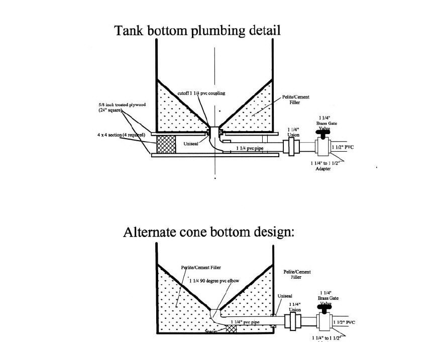
Schematic of two cone bottom designs.
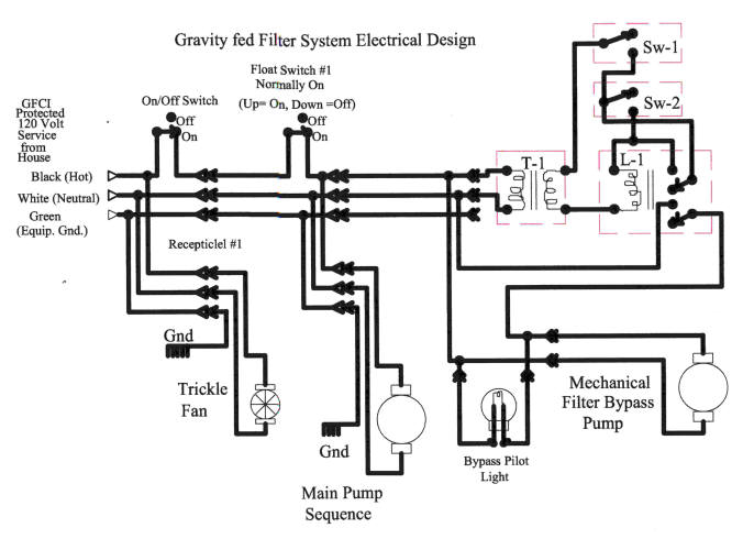
This
is a schematic of the circuitry used in the gravity fed filter. The design includes operation of a mechanical
filter bypass pump. Float switches s-1
and s-2 are positioned in the second vessel with s-1 at the normal fluid level
and s-2 at a lower level that would likely occur when the mechanical filter
becomes clogged. As the water level
drops, s-1 would turn on but the pump would not be energized until s-2 is also
turned on. The pump will continue to run
until the water level rises enough to turn off s-1.
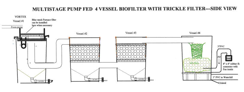
This
is a simpler submerged media filter system that could be fed by a submerged
pump. The water enters via a pipe
emptying into a mechanical filter. If
the mechanical filter becomes clogged, it will simply overflow into the vortex
vessel; therefore, no bypass pump is required.
Main pump protection would be accomplished by positioning a mercury
float switch in the pool itself to turn off the pump if the water level in the
pool should drop below a predetermined level.
As depicted in the schematic above, the drums would all sit on the
ground or on a raised area that would allow for an adequate drop for a
waterfall.
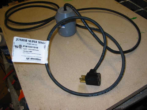
This picture
shows the mercury switch that is used to protect the main pump from running dry
as is it comes from the manufacturer.
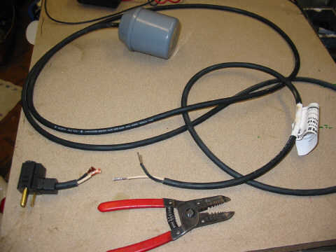
This shows the
plug removed from the mercury float switch.
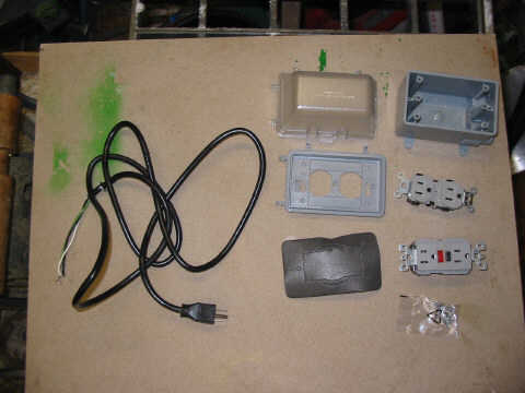
These are the
parts used to install the mercury float switch.
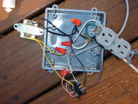
Here is the
wiring necessary for the mercury float switch.
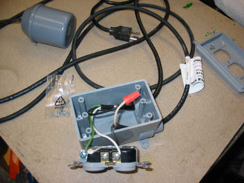
This shows the
completed wiring for the mercury float switch circuit for the main pump
protection circuit.
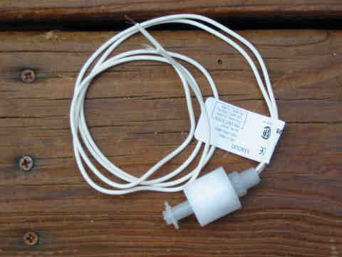
This is the
liquid level switch. It is used for the mechanical filter bypass because it is
more sensitive to changes in water level than the mercury float switches.
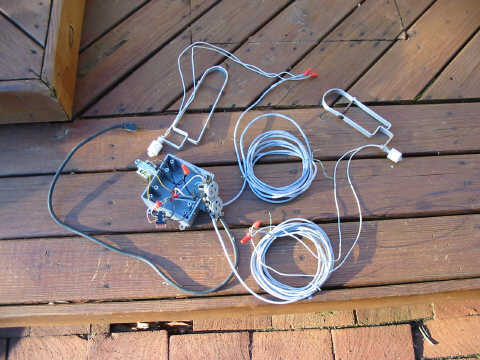
This is a picture of the circuitry for the mechanical
filter bypass.
Showing the wiring of the 12 volt ac transformer and
the relay.
All connections should be coated with liquid
electrical tape.
This shows the installed float switches for the
mechanical filter bypass pump.
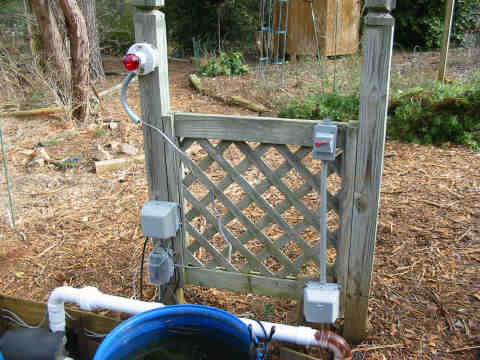
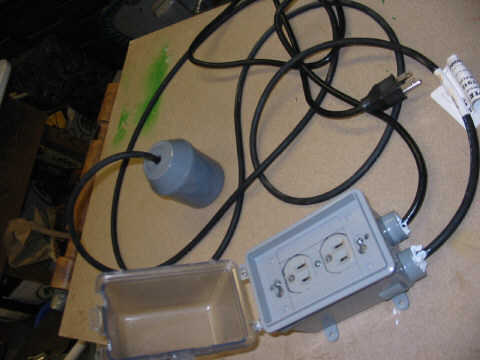
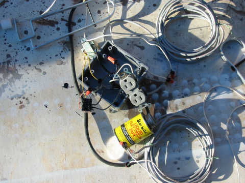
A
picture of the electrical services for the filter system. Note the red warning light for the mechanical
filter bypass pump. The red lever all weather
switch on the right side turns off all power to the system. The mercury float switch is plugged into the
switch controlled receptacle in the large box below the switch shown above. The receptacle on the bottom left is
controlled by the mercury float switch.
Plugged into it are the main pump and the power supply to the large box
above it on the left. The large upper
box contains the 12 volt transformer and the 12 volt ac operated relay that
controls the 120 volt power to a receptacle inside. The 12 volt ac relay circuit is controlled
with the two float switches as shown in the electrical schematic. Plugged in to the inside receptacle are the
Bypass pump and the red warning light.
The clamp visible on the rim of the pump reservoir drum is used to
adjust the operation of the mercury float switch.
MAINTENANCE:
Regular
maintenance is important to the operation of any watergarden. Face it, while the goal of practically all
hobby watergarden folks is to mimic mother nature and have a “natural”
appearing water garden, we must understand that lined water gardens are really
nothing more than outdoor aquariums. Maintaining
a healthy environment for our wet pets is our responsibility, not mother natures.
Step
1 is to monitor the screens in any skimmers in our pond system. /fish may be caught in skimmers and will have
to be freed. Accumulated debris must
also be regularly removed.
Step
2 is to monitor the mechanical filter to keep it free flowing and removing the
solids it collects. The system as
described above will help you in that regard by the warning light that comes on
whenever the mechanical filter bypass pump is called into action due to
mechanical filter clogging.
Step
3 is to monitor the batting in the water polisher and replace it any time the
wastebasket overflows.
Step
4 is to periodically open the gate valves one at a time that will drain from
each filter vessel cone bottom any detritus that has accumulated therein.
Step
5 is to at least twice annually removing the pump from the system and checking
to see if there is anything blocking the pump rotor such as water snail shells.
Step
6 is to annually replace the bulb in your UV light to keep any planktonian
algae under control. If you are in a
zone where temperatures drop to freezing, it is best to remove the UV unit from
the system during cold weather.
Step
7 is to periodically determine that the forced air fan in the trickle filter is
functioning.
Step
8 is the least often requirement. Performance
of this procedure should be done at least once annually and done only on one
media containing vessel at a time with an interval between vessels of at least
six weeks. Turn off power to the
system. Shut off flow from the pond by
closing the knife valves feeding the system.
Remove the top grid covering the media in the selected vessel. Reach in and grasp the bags holing the bio media
and pull up and down vigorously, dislodging accumulated sediments. Open the drain for that vessel and spray
water from a hose over the media to further wash sediment away. Note: you will
lose some water from other vessels in this process. Close the drain valve and add water to the
filter system until it is once again full.
Wait 1 hour to allow settling and turn power back on to the system.